Introduction
Every four years, the world gathers around the sport of soccer (or football), and the thrill of the FIFA World Cup simply takes over. The world's greatest football nations meet on the pitch, every player powered by patriotic will amongst the spirited crowds. Whether a die-hard or a bandwagon fan, no one can dispute the emotion that takes over when the ball sinks into the back of the net.
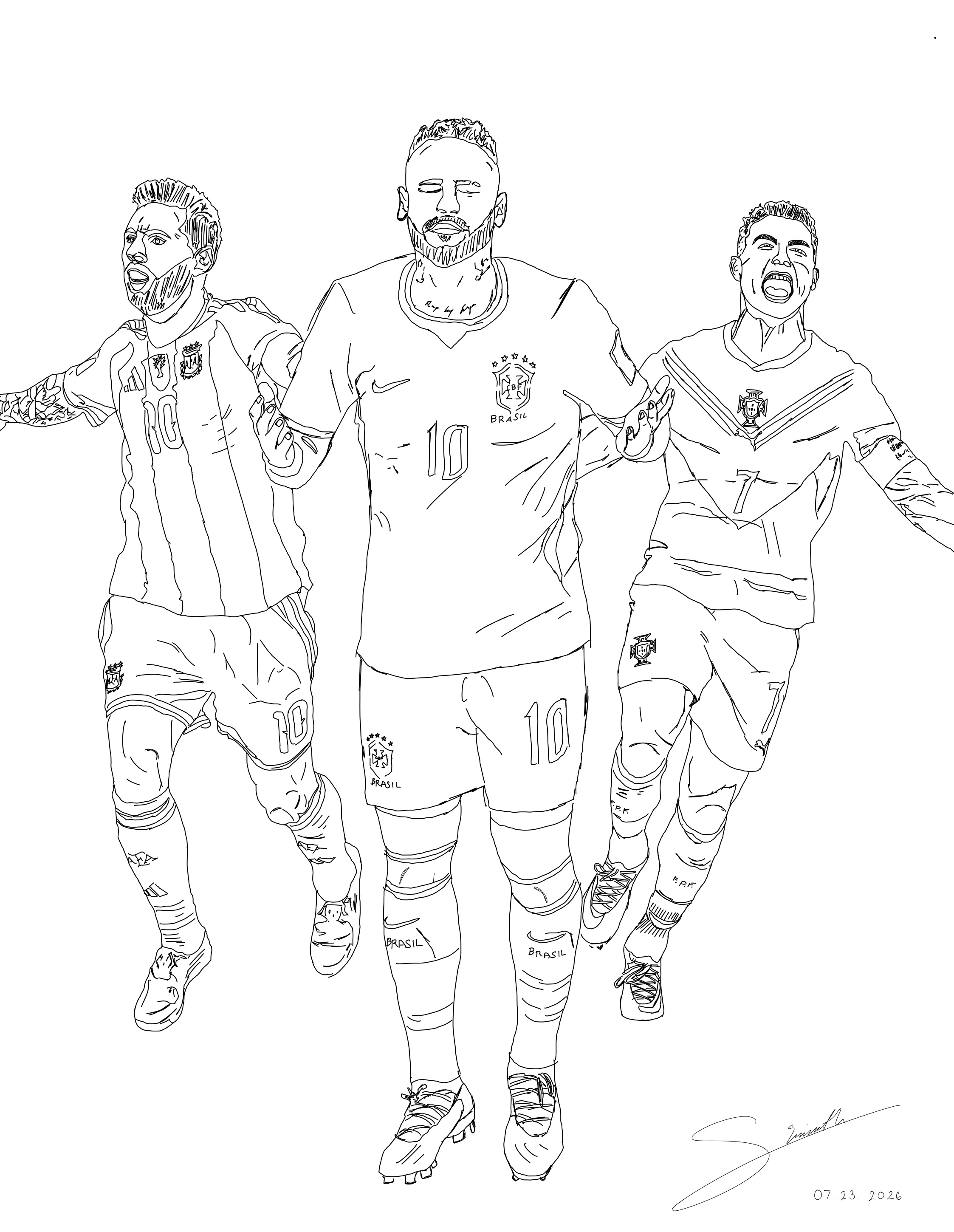
Naturally, it is the players that draw the eyes of the world; after all, they are the stars. As a young fan, it was the magic in Messi's touch, the style and flair in Neymar's movements, and the sheer power of Cristiano Ronaldo's strike that blew my mind away anytime the ball arrived at their feet. A minimum of 90 minutes of pure excitement, from kickoff to the final whistle, it truly never has disappointed.
Though that simplistic enjoyment still exists in my heart, it was something else that caught my eye in the most recent FIFA World Cup 2026. The sport of soccer has come a long way in the last few decades, specifically in regards to the technology that has arrived to assist in the regulation of the game. To aid the eyes of the referees, there are various different camera angles that help govern the field, allowing for remarkable tracking of the ball's exact position at any instant, a system known as Video Assistant Referee (VAR)[1]. But never did I expect that the ball itself was the latest addition to the innovation taking over the realm of football.
The 2026 World Cup ball, called the Trionda, is a masterful blend of aerodynamics and design. Translating to "three waves" in Spanish, it is representative of the first ever World Cup held by three host nations: the United States, Mexico, and Canada. The ball uses a thermally bonded polyurethane construction with a textured surface that optimizes durability, grip, and consistent aerodynamic performance. Its four-panel design uses deep seams that create evenly distributed drag, optimizing airflow and producing a more stable, predictable flight [2].
However, the marvel of the Trionda doesn't come from its colors, but rather inside. It hides a special treasure, which has served instrumental to the tournament, allowing for judgments that even the cameras cannot easily determine. Inside lies a rechargeable inertial measurement unit (IMU), sending live statistics of the ball's every movement at 500 samples a second, including shot speeds, spin rate, every precise touch, and more. [3]
It may not sound like a big deal, but as a STEM enthusiast, it blew my mind that they could keep such technology inside a ball. The first question of course is where could this be placed? For a ball to behave like an ordinary soccer ball, its center of mass should coincide with its geometric center. If not, the ball would roll, well simply put, weirdly. To demonstrate this, consider the simulation below. The standard soccer ball used in any regulation game has very strict standards, and this of course is what the players become accustomed to [4]. Even small changes will most certainly be noticeable to them.
The Simplest Scenario
Imagine the simplest scenario: a ball will roll after being kicked (let's just consider 2D for now). When subject to an impulse, the ball is set into motion, and begins to roll. A ball can be modelled as a hollow spherical shell, with some given thickness. Once the ball has been given an initial translational and rotational velocity, and neglecting friction, it continues to roll with constant speed and constant angular velocity, with its center of mass moving in a straight line:
Below the graph, we can see what all parameters are set to, including the radius and mass of the ball (taken default to be 11cm and 450g per regulation standards) [4] For now, the mass of the IMU chip is set to 0 to show that there is no internally placed mass. Then we give it some initial velocity under standard gravity, and we can observe the resulting rotational and translational position, angular velocity, and angular acceleration.
Without friction, it is free to roll forever this way, but let's now add in some reasoning with the IMU chip in order to see how the motion changes. We can experiment in the simulation how different masses change the kinematics of the ball. The following diagrams show roughly a chip that is 50%, 10% and then just 3% of the total mass of the ball.
Immediately a few things jump out. You no longer have a constant angular acceleration. There is now a varying torque that causes the ball's motion to be non-uniform. In an applied context, imagine trying to pass a ball to someone with a standard kick, and all of a sudden the ball is practically stopping and starting every few seconds…
The reason I show various masses for the internal chip is just to show how remarkably small the mass must be inside the ball. At 50% the mass of the ball, the chip causes significant oscillation in angular acceleration, and as we decrease this value to 10%, we still observe a noticeable oscillatory motion.
The final number 3% is representative of the real World Cup ball's IMU chip, weighing just 14 grams[5], and we see that even though the path of the COM (green trail) seems quite straight, there is still a variable angular acceleration.
Once again, these simulations show an oversimplified scenario in which many resistive forces (much harder to simulate) are omitted in order to demonstrate the sole effect of the offset center of mass. When including these forces such as rolling resistance, aerodynamic drag, or surface irregularities, the resulting motion can become far more complex.
So How Is the Chip Actually Placed?
So we can see that placing a chip inside a soccer ball is problematic even in the simplest scenario, which of course brings us to the question: what is the actual solution? How is this chip embedded in the ball?
The answer comes from simple geometry, and there have actually been two solutions used in the FIFA World Cup.
Back in 2022, the official FIFA World Cup ball was the Adidas Al Rihla, which also held an internal IMU chip. It was placed exactly at the center of the ball, suspended symmetrically from the surrounding spherical shell [6]. What this effectively does is bring the geometric center and the center of mass of the ball to the same location, and as long as the mass and composition of the ball's material are held accordingly, it would feel like there was no difference.
Though this setup fared well, it did struggle to withstand the impacts of a professional soccer match; for example the suspensions would snap under severe kinetic compressions that happen during a soccer match.
Therefore, the alternative option, used in the 2026 Trionda World Cup ball, was to place the chip directly on the inner surface of one of the four panels the ball is composed of. [7] This would eliminate the fragility issue by getting rid of the suspensions, but we know from the simulations that this would most certainly bring the geometric center and center of mass to two distinct points.
The solution is to correspondingly place counterweights on the remaining 3 panels in a symmetric manner such that the geometric center and center of mass once again come together at the center of the ball.
Through lengthy testing, it was made sure that players would never feel the difference between the IMU embedded balls and standard balls[8]. These points really come to show how carefully the World Cup ball has been engineered, and that even what appears to be the most simple object, actually carries such complexity.
Discussion
With the science established, the importance of these embedded chips doesn't end, as they made vital decisions throughout the tournament. As previously mentioned, the purpose of these chips is to provide live data of the balls every movement and position, and can detect even the smallest impulses in the air. At first glance, this may seem like an amazing addition, but I think there are definitely some points to be addressed with the integration of technology into live sports.
Notably in this recent World Cup, the embedded technology served crucial in the elimination of historic midfielder Luka Modric and Croatia in their matchup against the legendary Cristiano Ronaldo and Portugal[9].
In the fading minutes of stoppage time, Croatia found themselves trailing 2-1, and desperately needed an equalizer to keep their World Cup dream alive. Croatian veteran Ivan Perisic sent in a beautiful pass from the left wing, and the ball took a few deflections before finding the feet of Joško Gvardiol, and powered into the back of the Portuguese net.
It was a Croatian miracle, but it was short lived as the referee headed to the VAR and returned with a shocking decision. Prior to the ball striking the back of the net, only two deflections seemed to be visible: first off Portuguese defender Renato Veiga, then off the thigh of Croatian midfielder Mario Palasic, to the feet of Gvardiol into the net. This sequence deemed the goal onside and Croatia had successfully equalized.
However, the VAR had reviewed the play and with the help of the embedded IMU chip, was able to reveal a third prior touch that would make the sequence offsides: the hair of Croatian striker Igor Matanović had given the ball the slightest graze, and the consequence was the decision for an offsides call.
No camera angle could show the ball evidently strongly deflecting off Matanović's head, but it was the ball itself that came to make this decision. Visualizations of the actual impulse detected can be seen on FIFA's official replay footage of the match.
The chip made another essential decision in the quarter-final match between Norway and England [10]. Norway was leading 1-0, when keeper Ørjan Nyland sent out a goal kick deep into the right of the field, when all of a sudden the ball was seen to simply drop out of the air.
England seized the opportunity and within two passes, Jude Bellingham equalized, and would go on to later score England's second of the match for a 2-1 win, leading The Three Lions into the semi-finals.
A replay was shown, and it was visible that the ball seemed to hit something in the air, likely an overhead drone cable, and immediately drop. Typically, this would force play to stop, but when reviewed by VAR, it was already too late, and it was claimed that the embedded IMU chip did not detect any impulse at all[11].
So this presents an interesting situation, as the ball was able to detect the hair of a player, but not what seemed to be an evident collision with an overhead cable?
I share these two instances because they show the significance of the technology that has come to aid a sport cherished by the world, and brings into question what the role of technology should be in our sports.
As exceptional as the engineering and physics are behind La Trionda, we have to wonder where the line should be drawn for the in-game usage of these innovations, as they really seem to be making arguably harsh and imperative decisions that defy what we actually see.
Will we one day see matches where there are no human referees, and decisions are left entirely to the technology? Is technology removing the 'human aspect' that drives the enthusiasm and excitement behind the sports we love?
I feel the answer to these questions will definitely begin to show in upcoming years, as sports associations around the world begin integrating more technology into regular games. Sports as an institution will most certainly change in the years to follow, and I am excited to see the direction it evolves in.
The Physics Behind the Actual Simulation
As mentioned, the soccer ball itself is taken to be a hollow spherical shell, and we treat the internal IMU chip as a point mass \(M_{\text{IMU}}\) located at a distance \(R_{\text{IMU}}\) from the center of the ball.
We are considering planar rolling motion, so the ball rotates about an axis perpendicular to the plane of motion (into and out of the page). Under this assumption, the ball and the IMU behave as a rigid body sharing the same instantaneous angular velocity, and it is this orientation that allows us to make the simplification that the rotational inertia of the setup is that of a hollow sphere together with a point mass, together behaving as a rigid body about a common axis of rotation.
This gives:
Next, we need a coordinate system to track our ball in. We can denote \(x(t)\) to be our position of the center of the ball, and \(\theta(t)\) to be the angular rotation of the ball. As the ball rolls, the position is related to angular displacement by:
Equivalently, we can take time derivatives to write:
where \(\omega\) is the angular velocity of the ball. The point of contact between the ball and the ground is instantaneously at rest relative to the ground; this is the meaning of rolling without slipping.
Next, let's specify the position of the IMU within the shell. Its initial position can be specified using \(R_{\text{IMU}}\) and its initial angular orientation relative to the ball prior to rotation; call this angle \(\phi\).
The coordinates at some time \(t\) of the IMU chip relative to the center of the ball is then:
This means that coordinates in a standard frame of reference would be translated by the distance the ball's center has moved in each direction:
In order to get to the angular acceleration, we will first derive the torque from the potential energy given by the relation:
The potential energy comes from gravitational potential, and therefore we need both the potential energy of the ball and the IMU chip. Importantly here, we can recognize that the ball's geometric center remains at the same height above the ground, and for this reason, it will never change as it rolls.
However, the IMU chip has a constantly varying height as the ball rotates, and therefore, this is what produces the changes in potential energy, and consequently a varying torque.
Taking the height of the chip above the ground to be its y-coordinate, we have that the potential energy of the configuration is:
Taking the derivative with respect to \(\theta\), we find:
Now another way to find the torque is given by the rotational inertia of the system multiplied by the angular acceleration:
However, we can't simply use the \(I_{\text{total}}\) that we compute prior because this refers to only the inertia of rotation if our ball were spinning in place. We have to account for the fact that it is translating as well. To do so, we can look at kinetic energy.
The total kinetic energy of this configuration is the sum of both the rotational and translational energies. For just the rotational energy, we know that it is equivalent to:
And the translational energy will be:
Now given our rolling without slipping constraint, we can use the relation \(v = R_{\text{ball}}\omega\), and get that the translation kinetic energy can be rewritten as:
We can now express the total energy as:
Here, we make an important observation. Given this expression we can identify an effective inertia that is essentially the total inertia responsible for resisting the change in \(\omega\); that is the coefficient within the parenthesis:
This is to say that it is this total inertia that is responsible for the resistance to motion, and therefore should be used instead of just \(I_{\text{total}}\) in order to find the angular acceleration from the torque:
Given that \(\alpha\) is the second time derivative of the angular displacement, we have:
This expression here essentially serves as the driving equation of motion behind the simulation.
Using the explicit Euler Method, we can now solve for the motion of the ball under different initial conditions by incrementing over time steps:
So what we have now is a way to track the ball's motion over time, and are able to build a dataset for the ball and its relevant characteristics over time. The time step we use is determined by the framerate our animation runs in, which is set to 60 fps in the above visuals. The timestep is then simply 1/60 seconds; one over the frequency gives us the period for each frame.
The rest of the animation's visuals are simply extensions of the above generated data. At every timestep, the center of mass is computed from the weighted average of the ball's center and the IMU position. Plotting these successive positions produces both the instantaneous center of mass marker and the trail showing its path throughout the motion.
The stripe running from the geometric center to the end is simply plotted by specifying the location of the center and a point on the edge of the ball during each frame, and shows the rotation of the ball. I have left source code for the simulation available in a GitHub repository, and anyone is welcome to explore and modify it to their liking.
Disclaimers and Possible Future Additions
A Quick Note About the Model
The goal of this project wasn't to build a perfectly realistic model of a soccer ball on the pitch, but rather to isolate one interesting piece of physics and see what effect it has on the motion.
Like any simulation, this one makes a number of simplifying assumptions. The ball is treated as a perfectly rigid hollow shell, the IMU is modeled as a point mass fixed inside the ball, and the ball is assumed to roll without slipping.
Effects such as air resistance, rolling resistance, deformation of the ball, and energy losses are all ignored. We also approximate the translational kinetic energy using the motion of the ball's geometric center rather than the exact motion of the system's center of mass.
These assumptions keep the mathematics manageable while still capturing the primary effect we're interested in: how an offset internal mass influences the motion.
Furthermore, any references to specific values and occurrences are all cited from reputable sources, linked below.
Where Could This Go Next?
There are plenty of ways this model could be made more realistic. We could include aerodynamic drag, rolling resistance, or slipping between the ball and the ground.
The IMU could also be modeled as an object with its own size and shape instead of a point mass, and the equations of motion could be derived from a more complete Lagrangian treatment of the offset center of mass.
None of these additions are necessary to see the basic physics, but they would be interesting directions to explore in a future version of the simulation.
Notes & Sources
- FIFA, Video Assistant Referee System , Accessed August 2026. ↩
- Tharne, L., “FIFA World Cup ball: The science behind Adidas' Trionda” The Athletic, June 20, 2026. Accessed August 8, 2026. ↩
- FIFA, “Trionda - Official Match Ball | FIFA World Cup 2026™”. Accessed August 2026. ↩
- The International Football Association Board (IFAB), Law 2: The Ball - 2.1 Qualities and Measurements ↩ ↩
- Balsters R., Novagraaf, Lexology, Trionda®, the connected ball of the 2026 FIFA World Cup. Accessed August 2026. ↩
- Adidas, Adidas reveals the first FIFA World Cup™ official match ball featuring connected ball technology. Accessed August 2026. ↩
- Adidas, adidas Unveils 'Trionda' - the Official Match Ball of the Fifa World Cup26™ Accessed August 2026. ↩
- Borden, S. ESPN, "World Cup 'smart' ball is a game changer. Just remember to charge it" Accessed August 2026. ↩
- FOX Sports, FIFA World Cup 2026, Portugal vs Croatia Highlights 🌎🏆 2026 FIFA World Cup™ | Round of 32. Accessed August 2026. ↩
- FOX Sports, FIFA World Cup 2026, Norway vs England Highlights 🌎🏆 2026 FIFA World Cup™ | Quarterfinals. Accessed August 2026. ↩
- ESPN, FIFA Media, FIFA denies ball hit wire in England's first goal vs. Norway Accessed August 2026. ↩